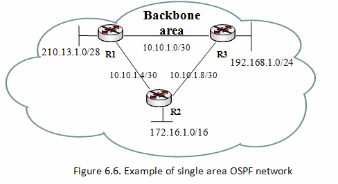
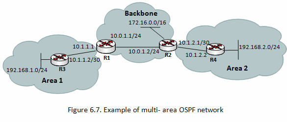
The following example illustrates how to configure single-area OSPF network. Let’s assume we have the following network.
Example network consists of 3 routers connected together within 10.10.1.0/24 network and each router has also one additional attached network.
In this example following IP addresses are configured:
 [admin@MikroTikR1]/ip address add address=10.10.1.1/24 interface=ether1
[admin@MikroTikR1]/ip address add address=10.10.1.5/24 interface=ether2
[admin@MikroTikR1]/ip address add address=210.13.1.0/28 interface=ether3
[admin@MikroTikR2]/ip address add address=10.10.1.6/24 interface=ether1
[admin@MikroTikR2]/ip address add address=10.10.1.9/24 interface=ether2
[admin@MikroTikR2]/ip address add address=172.16.1.0/16 interface=ether3
[admin@MikroTikR3]/ip address add address=10.10.1.2 /24 interface=ether1
[admin@MikroTikR3]/ip address add address=10.10.1.10/24 interface=ether2
[admin@MikroTikR3]/ip address add address=192.168.1.0/24 interface=ether3
There are three basic elements of OSPF configuration:
- Enable OSPF instance
- OSPF area configuration
- OSPF network configuration
General information is configured in /routing ospf instance menu. For advanced OSPF setups, it is possible to run multiple OSPF instances. Default instance configuration is good to start, we just need to enable default instance.
R1:
[admin@MikroTikR1] /routing ospf instance> add name=default
R2:
[admin@MikroTikR2] /routing ospf instance> add name=default
R3:
[admin@MikroTikR3] /routing ospf instance> add name=default
Show OSPF instance information:
[admin@MikroTikR1] /routing ospf instance> print
Flags: X - disabled
0   name="default" router-id=0.0.0.0 distribute-default=never
    redistribute-connected=as-type-1 redistribute-static=as-type-1
    redistribute-rip=no redistribute-bgp=no redistribute-other-ospf=no
    metric-default=1 metric-connected=20 metric-static=20 metric-rip=20
    metric-bgp=auto metric-other-ospf=auto in-filter=ospf-in
out-filter=ospf-out
As you can see router-id is 0.0.0.0, it means that router will use one of router's IP addresses as router-id. In most cases it is recommended to set up loopback IP address as router-id. Loopback IP address is virtual, software address that is used for router identification in network. The benefits are that loopback address is always up (active) and can’t be down as physical interface. OSPF protocol used it for communication among routers that identified by router-id. Loopback interface are configured as follows:
Create bridge interface named, for example, “loopback”:
[admin@MikroTikR1] /interface bridge> add name=loopback
Add IP address:
[admin@MikroTikR1] > ip address add address=10.255.255.1/32 interface=loopback
Configure router-id as loopback:
[admin@MikroTikR1] /routing ospf instance> set 0 router-id=10.255.255.1
This can be done on other routers (R2, R3) as well.
Next step is to configure OSPF area. Backbone area is created during RouterOS installation and additional configuration is not required.
And the last step is to add network to the certain OSPF area.
On R1
[admin@MikroTikR1] /routing ospf network> add network=210.13.1.0/28 area=backbone
[admin@MikroTikR1] /routing ospf network> add network=10.10.1.0/30 area=backbone
[admin@MikroTikR1] /routing ospf network> add network=10.10.1.4/30 area=backbone
Instead of typing in each network, you can aggregate networks using appropriate subnet mask. For example, to aggregate 10.10.1.0/30, 10.10.1.4/30, 10.10.1.8/30 networks, you can set up following ospf network:
[admin@MikroTikR1] /routing ospf network> add network=10.10.1.0/'''24''' area=backbone
R2:
[admin@MikroTikR2] /routing ospf network> add network=172.16.1.0/16 area=backbone
[admin@MikroTikR2] /routing ospf network> add network=10.10.1.0/24 area=backbone
R3:
[admin@MikroTikR3] /routing ospf network> add network=192.168.1.0/24 area=backbone
[admin@MikroTikR3] /routing ospf network> add network=10.10.1.0/24 area=backbone
You can verify your OSPF operation as follows:
- Look at the OSPF interface menu to verify that dynamic entry was created:
[admin@MikroTikR1] /routing ospf interface> print
- Check your OSPF neighbors, what DR and BDR is elected and adjacencies established:
[admin@MikroTikR1] /routing ospf neighbor> print
- Check router’s routing table (make sure OSPF routes are present):
[admin@MikroTik_CE1] > ip route print
Simple multi-area configuration
Backbone area is the core of all OSPF network, all areas have to be connected to the backbone area. Start configuring OSPF from backbone and then expand network configuration to other areas.
Lets assume that IP addresses are already configured and default OSPF instance is enabled.
All we need to do is:
- create an area
- attach OSPF networks to the area
R1 configuration:
/routing ospf> add name=area1 area-id=0.0.0.1
/routing ospf> add network=10.0.1.0/24 area=backbone
/routing ospf> add network=10.1.1.0/30 area=area1
R2 configuration:
/routing ospf> add name=area2 area-id=0.0.0.2
/routing ospf> add network=10.0.1.0/24 area=backbone
/routing ospf> add network=10.1.2.0/30 area=area2
R3 configuration:
/routing ospf> add name=area1 area-id=0.0.0.1
/routing ospf> add network=10.1.1.0/30 area=area1
R4 configuration:
/routing ospf> add name=area2 area-id=0.0.0.2
/routing ospf> add network=10.1.2.0/30 area=area2
Now you can check routing table using command /ip route print
Routing table on router R3:
[admin@R3] > ip route print
Flags: X - disabled, A - active, D - dynamic,
C - connect, S - static, r - rip, b - bgp, o - ospf, m - mme,
B - blackhole, U - unreachable, P - prohibit
#      DST-ADDRESS        PREF-SRC        GATEWAY            DISTANCE
1 ADo  10.0.1.0/24                        10.1.1.1           110
2 ADC  10.1.1.0/30         10.1.1.2       ether1             110
3 ADo  10.1.2.0/30                        10.1.1.1           110
4 ADC  192.168.1.0/24      192.168.1.1    ether2             0
As you can see remote networks 172.16.0.0/16 and 192.168.2.0/24 are not in the routing table, because they are not distributed by OSPF. Redistribution feature allows different routing protocols to exchange routing information making possible, for example, to redistribute static or connected routes into OSPF. In our setup we need to redistribute connected network. We need to add following configuration on routers R1, R2 and R3.
[admin@R3] /routing ospf instance> set 0 redistribute-connected=as-type-1
[admin@R3] /routing ospf instance> print
Flags: X - disabled
0   name="default" router-id=0.0.0.0 distribute-default=never
    redistribute-connected=as-type-1 redistribute-static=no
    redistribute-rip=no redistribute-bgp=no redistribute-other-ospf=no
    metric-default=1 metric-connected=20 metric-static=20 metric-rip=20
    metric-bgp=auto metric-other-ospf=auto in-filter=ospf-in
    out-filter=ospf-out
Now check router R3 to see if routes 192.168.2.0/24 and 172.16.0.0/16 are installed in routing table.
[admin@R3] > ip route print
Flags: X - disabled, A - active, D - dynamic,
C - connect, S - static, r - rip, b - bgp, o - ospf, m - mme,
B - blackhole, U - unreachable, P - prohibit
#      DST-ADDRESS        PREF-SRC        GATEWAY            DISTANCE
1 ADo  10.0.1.0/24                        10.1.1.1           110
2 ADC  10.1.1.0/30         10.1.1.2       ether1             110
3 ADo  10.1.2.0/30                        10.1.1.1           110
4 ADo  172.16.0.0/16                      10.1.1.1           110
5 ADC  192.168.1.0/24      192.168.1.1    ether2             0
6 ADo  192.168.2.0/24                     10.1.1.1           110
NBMA networks
OSPF network type NBMA (Non-Broadcast Multiple Access) uses only unicast communications, so it is the preferred way of OSPF configuration in situations where multicast addressing is not possible or desirable for some reasons. Examples of such situations:
- in 802.11 wireless networks multicast packets are not always reliably delivered (read Multicast_and_Wireless for details); using multicast here can create OSPF stability problems;
- using multicast may be not efficient in bridged or meshed networks (i.e. large layer-2 broadcast domains).
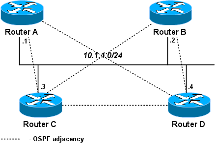
Especially efficient way to configure OSPF is to allow only a few routers on a link to become the designated router. (But be careful - if all routers that are capable of becoming the designated router will be down on some link, OSPF will be down on that link too!) Since a router can become the DR only when priority on it's interface is not zero, this priority can be configured as zero in interface and nbma-neighbor configuration to prevent that from happening.
In this setup only C and D are allowed to become designated routers.
On all routers:
routing ospf network add network=10.1.1.0/24 area=backbone
routing ospf nbma-neighbor add address=10.1.1.1 priority=0
routing ospf nbma-neighbor add address=10.1.1.2 priority=0
routing ospf nbma-neighbor add address=10.1.1.3 priority=1
routing ospf nbma-neighbor add address=10.1.1.4 priority=1
(For simplicity, to keep configuration the same on all routers, nbma-neighbor to self is also added. Normally you wouldn't do that, but it does not cause any harm either.)
Configure interface priorities. On routers A, B:
routing ospf interface add interface=ether1 network-type=nbma priority=0
On routers C, D (they can become the designated router):
routing ospf interface add interface=ether1 network-type=nbma priority=1
Results
On Router A:
[admin@A] > routing ospf neighbor print
0 router-id=10.1.1.5 address=10.1.1.5 interface=ether1 priority=1 dr-address=10.1.1.4
  backup-dr-address=10.1.1.3 state="Full" state-changes=6 ls-retransmits=0
  ls-requests=0 db-summaries=0 adjacency=4m53s

1 router-id=10.1.1.3 address=10.1.1.3 interface=ether1 priority=1 dr-address=1.1.1.4
  backup-dr-address=10.1.1.3 state="Full" state-changes=6 ls-retransmits=0
  ls-requests=0 db-summaries=0 adjacency=4m43s

2 address=10.1.1.2 interface=ether1 priority=0 state="Down" state-changes=2

3 address=10.1.1.1 interface=ether1 priority=0 state="Down" state-changes=2
On Router D:
[admin@D] > routing ospf neighbor print
0 address=10.1.1.4 interface=ether1 priority=1 state="Down" state-changes=2

1 router-id=10.1.1.3 address=10.1.1.3 interface=ether1 priority=1 dr-address=10.1.1.4
  backup-dr-address=10.1.1.3 state="Full" state-changes=6 ls-retransmits=0
  ls-requests=0 db-summaries=0 adjacency=6m8s

2 router-id=10.1.1.2 address=10.1.1.2 interface=ether1 priority=0 dr-address=10.1.1.4
  backup-dr-address=10.1.1.3 state="Full" state-changes=5 ls-retransmits=0
  ls-requests=0 db-summaries=0 adjacency=6m4s

3 router-id=10.1.1.1 address=10.1.1.1 interface=ether1 priority=0 dr-address=10.1.1.4
  backup-dr-address=10.1.1.3 state="Full" state-changes=5 ls-retransmits=0
  ls-requests=0 db-summaries=0 adjacency=6m4s
OSPF Forwarding Address
OSPF may take extra hops at the boundary between OSPF routing domain and another Autonomous System. By looking at the following illustration you can see that even if router R3 is directly connected, packets will travel through the OSPF network and use router R1 as a gateway to other AS.
To overcome this problem, concept of OSPF forwarding-address was introduced. This concept allows to say "Send traffic directly to router R1". This is achieved by setting forwarding address other than itself in LSA updates indicating that there is an alternate next-hop. Mostly all the time forwarding address is left 0.0.0.0, suggesting that the route is reachable only through the advertising router.


0 comments:
Post a Comment